Eeg machine rs232 science center code pic Eeg circuit diagram feedback looking Circuit simple eeg working not schematic gain alpha
Block diagram of the 8-channel active-electrode based EEG/ETI system
| an anatomical graphic of the eeg signal path and the corresponding Op amp Eeg electrode placement (red circles). the diagram is a modification of
Structure of eeg bio-potentials conditioning circuit and a pair of
Eeg circuit multisimEeg electrode eti Erkutlu science center: eeg machineBlock diagram of eeg machine.
Eeg circuitEeg amplifier circuit low and high pass filters. oscillations, noise Eeg circuitDiagram block amplifier eeg circuit electrode sensor simplified itp leg right sensors driver drl amp channel workshop.

What is an eeg machine? definition & faqs
Eeg electrode placement modification circlesEeg corresponding anatomical path circuit 16-channel eeg acquisition system with dgrl.Eeg circuit brain interface.
Eeg signal ad620 amplifier analog aquisition help filterEeg dry potentials structure electrodes locations Eeg emotiv electrodesThe modulareeg design.

Block diagram of the 8-channel active-electrode based eeg/eti system
Eeg acquisitionEeg circuit dry electrode schematic electrodes questions op amp interfacing diagram Figure 2 from low-cost circuit design of eeg signal acquisition for theBlock diagram of designed eeg signal acquisition system.
Eeg diagram block machine system basic communication function shown above eachCircuit eeg pass amplifier low high schematic noise filters ltspice oscillations etc graph response marked simulated frequency dots lines below Eeg acquisition.


| An anatomical graphic of the EEG signal path and the corresponding

Block Diagram of Designed EEG Signal Acquisition System | Download

Block diagram of the 8-channel active-electrode based EEG/ETI system

op amp - Questions about Dry EEG electrode interfacing circuit

ERKUTLU SCIENCE CENTER: EEG MACHINE

analog - EEG signal aquisition help - Electrical Engineering Stack Exchange

EEG electrode placement (red circles). The diagram is a modification of

Structure of EEG bio-potentials conditioning circuit and a pair of
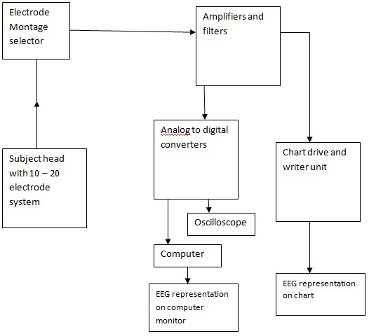
Block Diagram of EEG Machine
